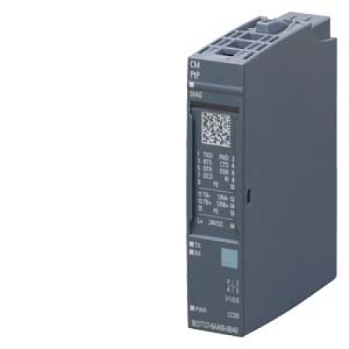

This tutorial focuses on designing a practical point-to-point (PtP) serial interface using the Siemens 6ES7137-6AA01-0BA0 module. This component is a PROFINET-capable IO module with a built-in PtP serial port, making it ideal for connecting industrial equipment like barcode scanners, printers, or weigh scales to a PLC. Its key suitability for this tutorial lies in its integrated isolation, configurable RS232/RS485/RS422 modes, and robust Siemens design, eliminating the need for external signal conditioners in many simple serial links. We will design a circuit to interface this module with an RS232 device, focusing on a standard 9-pin D-sub connection.
Design Requirements and Specifications
Our practical circuit must meet these specifications: The PtP interface operates at a default baud rate of 9600 bps, with 8 data bits, no parity, and 1 stop bit (8N1). The module's serial port is electrically isolated and provides a 24V DC supply for the interface (pin 9 on the D-sub). We need a circuit that ensures proper signal levels for RS232 (±3V to ±15V) while maintaining galvanic isolation. The key requirements are: supply voltage 24V DC (±20%), serial data rate up to 115200 bps, cable length up to 15 meters, and protection against short circuits and electrostatic discharge (ESD). The design must include a DB9 female connector, a line driver/receiver for RS232 level conversion, and proper termination for the PtP module's internal circuitry.
Step-by-Step Design Process with Calculations
First, determine the RS232 voltage levels. The module's PtP port outputs TTL-level signals (0-5V) on its internal side. We need a converter to shift these to RS232 levels. Select a standard RS232 line driver like the MAX232, which uses charge pumps to generate ±10V from a single 5V supply. Calculate the charge pump capacitor values: for the MAX232, use 1µF ceramic capacitors for C1, C2, C3, and C4 as per the datasheet. The typical output swing is ±8V, sufficient for RS232. Next, design the power supply: the module provides 24V on pin 9. Use a 7805 linear regulator to step down to 5V for the MAX232. Calculate the regulator's heat dissipation: at 5V output and 10mA load (MAX232 typical), power dissipation is (24V - 5V) * 0.01A = 0.19W, well within a TO-220 package without heatsink. Add a 100µF electrolytic capacitor at the 7805 input and a 10µF at the output for stability. For ESD protection, add TVS diodes (e.g., PESD5V0S1UB) on the RS232 lines (pins 2 and 3 of DB9). Finally, calculate the series resistor for the module's 24V output: if we draw 50mA maximum, a 100Ω resistor in series with a 5.1V zener diode can provide a crude 5V supply, but the 7805 is more reliable.
Component Selection Rationale for the Complete BOM
The Bill of Materials (BOM) is chosen for reliability and common availability. Core components: MAX232ACPE (DIP-16) for RS232 conversion - it is industry-standard, cheap, and has proven ESD tolerance. Power supply: LM7805CT (TO-220) for 5V regulation - robust with built-in thermal shutdown. Capacitors: 1µF ceramic (X7R, 50V) for the MAX232 charge pumps, 100µF/35V aluminum electrolytic for input filtering, 10µF/25V ceramic for output. Connector: DB9 female connector with metal shell for grounding (e.g., Amphenol 17E-09P). Protection: PESD5V0S1UB (SOD-323) TVS diodes for ESD on serial lines. Passives: 100Ω 1/4W resistor for module's 24V pin current limiting, 10kΩ 1/4W pull-up resistor on the module's RTS line (pin 7) to enable transmission. PCB: Use a 2-layer board with ground plane for noise immunity. This BOM minimizes cost while ensuring industrial-grade performance.
Simulation Tips and What to Look For
Simulate the RS232 driver circuit using LTspice or Multisim. Model the MAX232 using its SPICE model (available from Maxim). Key simulation checks: verify the charge pump outputs reach at least ±7V under load. Apply a 9600 bps square wave (TTL level) to the driver input; observe the output at the DB9 pin 2 (TxD) - it should swing between approximately -8V (mark) and +8V (space). Check for signal integrity: the rise time should be less than 30µs for 9600 bps. Add a 3kΩ load resistor to simulate a typical RS232 receiver (input impedance 3-7kΩ) and confirm voltage levels remain above ±3V. Simulate the power supply: at 24V input, the 7805 output should be 5V ±2% with a 50mA load. Look for ripple: less than 10mV peak-to-peak is acceptable. For ESD simulation, inject a 2kV transient through a coupling capacitor (150pF) on the serial line; the TVS diode should clamp voltage to below 10V. Ensure no latch-up occurs in the MAX232 by checking supply current remains stable.
Prototype Build and Testing Methodology
Build the circuit on a solderless breadboard for initial testing. First, populate the power supply section: connect the 24V from the module's pin 9 (via a 100Ω resistor) to the 7805 input. Measure +5V output with a multimeter. Next, wire the MAX232: connect its VCC to +5V, GND to 0V, and add the four 1µF capacitors to pins 1-6. Connect the module's TxD (pin 2 on the PtP port) to MAX232 pin 11 (T1IN). Connect MAX232 pin 14 (T1OUT) to DB9 pin 2 (TxD). For the receive path, connect DB9 pin 3 (RxD) to MAX232 pin 13 (R1IN), then MAX232 pin 12 (R1OUT) to the module's RxD (pin 3). Connect DB9 pin 5 (GND) to circuit ground. Add the TVS diodes across pins 2 and 3 to ground. For testing, use a terminal program (e.g., Tera Term) on a PC with a USB-to-RS232 adapter. Set the PC to 9600 8N1 and send "Hello" every second. On the PtP module, configure the same parameters using Siemens TIA Portal. Monitor the module's receive buffer in TIA Portal's watch table. Verify that the received string matches. Swap roles: send from the PtP module and check on the PC terminal. Test at 115200 bps for high-speed verification.
Performance Verification and Optimization
Measure signal quality with an oscilloscope. Probe the RS232 lines at the DB9 connector: the idle state should be a logic 1 (negative voltage, around -8V). A transmitted byte should show a start bit (positive swing), 8 data bits, and a stop bit (negative). Check for overshoot: should be less than 2V. If overshoot exceeds this, add a 100pF capacitor across the MAX232 output to ground as a low-pass filter. Measure the bit timing: at 9600 bps, each bit is 104µs. Use the scope's cursors to verify the pulse width is within 104µs ±5%. If timing is off, check the crystal or clock source if using a UART; here the module's internal clock is accurate. For optimization, reduce the charge pump capacitor value from 1µF to 0.47µF if the output voltage is too high (above ±10V), but the standard value works well. Add a ferrite bead (e.g., 60Ω at 100MHz) in series with the 24V line to suppress high-frequency noise from the module's switching regulator. Finally, test cable length: use a 15-meter shielded RS232 cable with the shield connected to DB9 pin 1 (which we tied to ground). If errors occur, reduce baud rate to 4800 or add a line driver like the DS3695 for longer distances. This design provides a reliable, noise-immune serial link for industrial automation.