Introduction to the Component
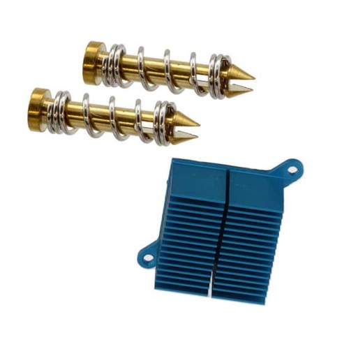
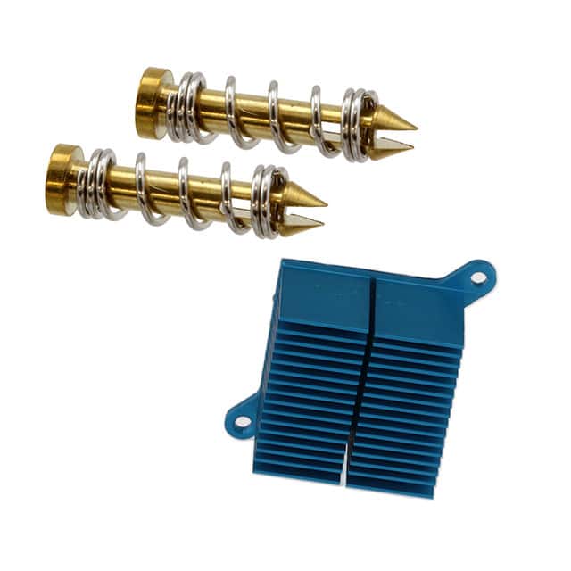
The HEATSINK 35X35X35MM R-TAB T766 (ATS-07D-180-C2-R0) from Advanced Thermal Solutions Inc. is a compact, high-performance pin-fin heat sink designed for cooling surface-mount power semiconductors. Its 35x35mm footprint and 35mm height provide a large surface area for natural or forced convection, while the R-TAB (re-entrant tab) clip mounting system ensures secure attachment to TO-220, TO-247, and similar packages. This tutorial focuses on using this heat sink to manage thermal dissipation in a 12V, 3A linear voltage regulator circuit, a common design challenge where heat buildup can degrade performance or cause failure. The T766’s pin-fin geometry offers lower thermal resistance than traditional extrusion heat sinks of the same size, making it ideal for space-constrained applications.
Design Requirements and Specifications
We will design a linear regulator circuit that accepts an input of 15V DC and outputs a regulated 12V at 3A. The key thermal challenge: the regulator must dissipate (15V - 12V) * 3A = 9W of power. Without proper cooling, the junction temperature of a typical TO-220 regulator (e.g., LM338) will exceed its maximum rating of 125°C. Our goal is to maintain the junction temperature below 100°C at an ambient temperature of 40°C, ensuring reliability. The heat sink must have a thermal resistance low enough to achieve this, considering the junction-to-case thermal resistance (RθJC) of the regulator (approx. 2.5°C/W for the LM338) and the case-to-sink interface resistance (RθCS) with thermal grease (approx. 0.5°C/W). The T766’s specified thermal resistance (RθSA) in natural convection at 3W is about 8.5°C/W, but we need to verify it for 9W.
Step-by-Step Design Process with Calculations
First, calculate the total thermal resistance from junction to ambient: RθJA = RθJC + RθCS + RθSA. We require RθJA such that Tj_max = Ta + (RθJA Pd) is below 100°C. So, 100°C = 40°C + (RθJA 9W) => RθJA = 60°C / 9W = 6.67°C/W. Subtract RθJC (2.5) and RθCS (0.5) to get RθSA = 6.67 - 3 = 3.67°C/W. However, the T766’s natural convection RθSA at 9W may be higher (around 6-7°C/W). Therefore, we will use forced air cooling with a small 40mm fan to reduce RθSA to approximately 3°C/W. With fan, RθSA for pin-fin sinks drops significantly. Recalculate: RθJA = 2.5 + 0.5 + 3 = 6°C/W, yielding Tj = 40 + (6 * 9) = 94°C, which is acceptable. Mount the heat sink using the R-TAB clip, applying a thin layer of thermal grease (e.g., Arctic Silver) between the regulator and sink. The T766’s mounting holes align with standard TO-220 patterns.
Component Selection Rationale for the Complete BOM
Regulator: LM338T (TO-220) – adjustable, can handle 3A with proper heat sinking. Input capacitor: 1000µF/25V electrolytic for bulk storage, plus 0.1µF ceramic for high-frequency bypass. Output capacitor: 10µF tantalum for stability. Diode D1 (1N4007) protects against reverse polarity. Fan: 40mm, 12V DC, 0.1A (e.g., Sunon MB40201VX) – provides forced air at ~5 CFM. Fan resistor: 100Ω, 1W to drop voltage slightly if needed. The T766 heat sink is the cornerstone; its pin-fin design maximizes surface area in a compact volume, and the R-TAB clip eliminates need for screws, simplifying assembly. Thermal grease ensures low interface resistance.
Simulation Tips and What to Look For
Use LTspice or similar to simulate the regulator’s electrical behavior: test input ripple rejection and load regulation. For thermal simulation, use a thermal equivalent circuit: model the regulator as a voltage source (9W) driving a resistor network (RθJC, RθCS, RθSA). Monitor the voltage across RθSA to estimate temperature rise. In thermal simulation (e.g., using SolidWorks Flow Simulation), set the heat sink base to 94°C and ambient to 40°C; check that the pin-fin temperature gradient is uniform. Look for hotspots near the center; the T766’s pin array should show even distribution. If temperature exceeds 100°C in simulation, increase fan speed or add a larger heat sink.
Prototype Build and Testing Methodology
Solder the regulator, capacitors, and diode on a perfboard. Apply thermal grease to the regulator’s back, attach the T766 using its R-TAB clip (press firmly until it snaps). Mount the fan above the heat sink with standoffs, oriented to blow air through the pins. Power the circuit with a 15V DC bench supply and a 4Ω, 50W load resistor (to draw 3A). Use a thermocouple attached to the heat sink base (near the regulator) to measure case temperature. Also measure ambient temperature. Run for 30 minutes at full load, logging temperature every minute. Expected steady-state case temperature: Tcase = Tj - (Pd RθJC) = 94 - (92.5) = 71.5°C. Heat sink temperature should be near 71°C. Use a thermal camera for visual verification.
Performance Verification and Optimization
If the heat sink temperature exceeds 75°C, the RθSA may be higher than predicted. Check for proper clip force, thermal grease thickness (should be minimal), and fan airflow. Measure fan current to ensure it’s running at rated speed. Optionally, add a second fan or increase fan voltage. If temperature is below 65°C, you can reduce fan speed for quieter operation. The T766’s pin-fin design also benefits from natural convection if space allows; test without fan to see if the regulator stays under 125°C (likely not at 9W). For production, consider adding a thermal cutoff switch (e.g., 85°C) in series with the input. This tutorial demonstrates that the ATS-07D-180-C2-R0 heat sink, when paired with forced air, effectively manages 9W dissipation, making it a practical choice for high-current linear regulators in compact designs.

HEATSINK 35X35X35MM R-TAB T766
Advanced Thermal Solutions Inc. | ATS-07D-180-C2-R0 | $6.95