Typical Failure Modes and Root Causes
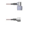
The TXR40AU00-2012BI, a TE Connectivity RF coaxial connector (often used in harsh environments), typically fails due to mechanical stress, poor soldering, or environmental contamination. The most common failure mode is intermittent electrical continuity, which manifests as a fluctuating VSWR (Voltage Standing Wave Ratio) or signal loss at higher frequencies. Root causes include cracked solder joints at the center pin or outer shield due to thermal cycling or vibration, corrosion of the contact surfaces if exposed to moisture or salt spray without proper sealing, and dielectric breakdown from voltage surges or arcing across the insulator. Another frequent issue is mechanical deformation of the coaxial interface, often caused by over-torquing during installation, which can compress the center pin or distort the outer conductor, leading to impedance mismatch.
Step-by-Step Debugging Methodology
Start with a visual inspection under a microscope (10x to 40x magnification). Look for cracked solder, missing or misaligned center pin, or discoloration from overheating. Next, perform a continuity check with a multimeter: measure resistance between the center pin and shield—it should be infinite (open circuit) in an unconnected state. If you see a short (< 1 ohm), suspect solder bridging or a damaged insulator. Then, use a Time Domain Reflectometer (TDR) or a network analyzer to measure impedance. For a 50-ohm system, the connector should show a characteristic impedance of 50 ohms ± 5 ohms. A sudden impedance dip or rise indicates a mechanical defect. Finally, conduct a signal integrity test at the operating frequency (e.g., 2.4 GHz for Wi-Fi) using a spectrum analyzer and a known-good signal source. Compare the insertion loss and return loss to the datasheet specifications.
Common Mistakes in Schematic Design and PCB Layout
A frequent error is incorrect footprint dimensions for the TXR40AU00-2012BI. The landing pattern must match the connector's pin pitch and shield grounding tabs exactly; a mismatch can cause poor solder wetting or shorts. Another mistake is insufficient grounding via stitching around the connector's shield. For high-frequency circuits, use at least four ground vias placed symmetrically around the shield to minimize ground inductance. Additionally, ignoring the trace width-to-gap ratio for the microstrip line leading to the connector can cause impedance discontinuities. Ensure the trace width and dielectric thickness adhere to the 50-ohm design rules. A common layout error is placing the connector too close to board edges, making it prone to mechanical stress during handling.
How to Verify Component Authenticity and Quality
Counterfeit TXR40AU00-2012BI connectors often have poor plating quality (e.g., gold plating that is too thin or inconsistent). Use a X-ray fluorescence (XRF) analyzer to check metal composition—authentic connectors have a specific gold thickness (typically 50 microinches minimum on the center pin). Compare the visual markings on the connector body: genuine TE parts have laser-engraved part numbers with consistent font and depth. Also, measure the insertion force during mating; counterfeit connectors often require significantly less force or feel gritty. For lot-level verification, request a Certificate of Conformance (CoC) from your distributor and cross-reference the date code with TE's official records.
Measurement Techniques and Test Equipment
For RF measurements, use a vector network analyzer (VNA) calibrated with a full two-port calibration kit (including the connector's specific test fixture). Measure S11 (return loss) and S21 (insertion loss) across the frequency band. For example, at 3 GHz, the return loss should be better than -20 dB. A digital oscilloscope with a high-impedance probe (e.g., 50-ohm input) can detect signal reflections if you use a TDR module. For DC testing, a four-wire Kelvin measurement is essential to accurately measure contact resistance below 10 milliohms. Always use calibrated test cables with low loss and ensure the connector under test is clean and dry.
When to Suspect the Component vs. the Surrounding Circuit
Suspect the TXR40AU00-2012BI first if the failure is intermittent and correlates with mechanical movement or temperature changes. If the failure is consistent across multiple boards with different components, the issue is likely in the PCB layout or signal path. For instance, if you measure a high VSWR at the connector but the trace impedance is correct, the connector itself may have a damaged dielectric. However, if the VSWR degrades only when the connector is mated to a specific cable, the problem is in the mating interface—check for worn or bent pins. Always swap the connector with a known-good unit from the same lot to isolate the defect.
Real-World Case Studies of Common Problems and Solutions
Case 1: A customer reported intermittent signal loss in a base station antenna. After visual inspection, we found cracks in the solder joint at the shield ground due to thermal expansion. The solution was to use a larger solder fillet and add a mechanical strain relief (e.g., a dab of epoxy). Case 2: In a high-vibration automotive application, the center pin of the connector was backing out after repeated thermal cycles. The root cause was a loose retention clip in the connector housing. Replacing the connector with a version that had a stronger retention mechanism solved the issue. Case 3: A prototype PCB showed high insertion loss at 5 GHz. The TDR revealed a 50-ohm impedance bump to 65 ohms at the connector footprint. Replacing the connector with a properly specified one and adding two additional ground vias brought the impedance back to spec. Case 4: A production run had random shorts between the center pin and shield. XRF analysis revealed poor gold plating on a counterfeit batch. Switching to an authorized distributor with lot traceability eliminated the problem.