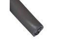

This guide addresses common issues when using the Omron E2F-X10E2 inductive proximity sensor (10mm sensing range, IP68, NPN/PNP depending on variant). The key to efficient debugging is a systematic approach, as many symptoms point to application or wiring problems rather than a defective sensor.
Typical Failure Modes and Root Causes:
The most common failure is the sensor failing to detect a metal target at the rated 10mm distance. Root causes include an incorrect target material (it must be ferrous or magnetic, not aluminum or brass), a target that is too small (the E2F-X10E2 requires a standard target of 30mm x 30mm), or excessive lateral misalignment. Another frequent issue is false triggering or oscillation, often caused by severe electrical noise from nearby motors, inverters, or switching power supplies. Physical damage, such as a cracked housing or crushed cable, can occur from overtightening the mounting nut (torque should not exceed 10 N·m) or from impact in harsh environments. Finally, sensor death—no output at all—is often due to reverse polarity (the brown wire is +V, blue is 0V, black is output) or overvoltage (exceeding 24V DC ±10%).
Step-by-Step Debugging Methodology:
Start with a visual inspection. Look for cracks in the epoxy face, bent pins, or cuts in the cable. Next, verify power. Using a multimeter, measure between the brown and blue wires. You should see a stable 12-24V DC. If the voltage is below 10V or oscillating, the power supply is the problem. Then, test the output. Connect the black wire to your multimeter (set to DC volts) and the blue wire to the meter’s common. With no metal target, the output should be 0V (for NPN) or supply voltage (for PNP). Place a steel target (a 30mm washer works well) directly on the sensing face. The output should switch state. If it doesn't, check the load impedance. The sensor is designed for loads > 10kΩ. A low-resistance load (e.g., a relay coil without a flyback diode) can clamp the output. Finally, check the sensing distance. Use a non-metallic ruler and a standard target. The sensor should trigger reliably at 8-10mm. If it only works at 2mm, the target material is likely wrong or the sensor face is contaminated.
Common Mistakes in Schematic Design and PCB Layout:
A critical mistake is omitting a flyback diode across inductive loads (relays, solenoids). Without it, the back-EMF from the load can destroy the sensor’s output transistor. In a schematic, always place a 1N4007 diode (cathode to +V, anode to output) in parallel with the load. Another error is using excessively long cable runs (over 100 meters) without considering voltage drop. The E2F-X10E2’s cable is 2 meters; extending it with thin wire can cause voltage sag. For PCB layouts, avoid routing high-current traces or noisy digital lines (like PWM signals) within 10mm of the sensor’s input connector. Capacitive coupling can cause false triggers. Also, never share the sensor’s 0V return path with a high-current motor return. Use a dedicated ground wire from the power supply.
How to Verify Component Authenticity and Quality:
Counterfeit Omron sensors are common on gray markets. First, check the packaging. Genuine Omron parts come in a sealed bag with a holographic Omron logo and a lot number printed in ink that does not rub off. Second, inspect the sensor body. The laser-etching of the model number (E2F-X10E2) and the IP68 rating should be crisp and deep. Counterfeits often have blurry print or a glossy surface. Third, measure the internal resistance. Using a multimeter, measure between the brown and blue wires. A genuine sensor will show a high resistance (typically > 1MΩ) when not powered. Counterfeits may show a short or an open circuit. Finally, test the sensing range. A genuine E2F-X10E2 will reliably detect a 1mm thick steel plate at 10mm. A counterfeit might only detect at 5mm or intermittently.
Measurement Techniques and Test Equipment:
A digital multimeter (DMM) is essential. Use it to measure DC voltage (brown-blue) and output voltage (black-blue). For dynamic testing, an oscilloscope is invaluable. Connect a probe to the black wire and trigger on a rising edge. Observe the output waveform. A clean, sharp transition from 0V to 24V (or vice versa) indicates a healthy sensor. A noisy, oscillating, or slow-rising signal suggests a wiring issue, a faulty load, or external interference. A current clamp can also be useful; the E2F-X10E2 draws about 15mA when active. If the current is much higher, the sensor may be damaged. For ground-loop issues, use a differential probe or measure between the sensor's 0V and the PLC’s 0V; a voltage difference greater than 1V AC indicates a problematic ground potential.
When to Suspect the Component vs. the Surrounding Circuit:
Suspect the sensor itself if all power and wiring checks are correct, the load is within spec, and the target is proper, but the output remains stuck in one state. A genuine sensor that fails in this manner is rare (less than 0.5% failure rate). More often, suspect the surrounding circuit if: the sensor works on a lab bench but not in the machine (indicating noise or grounding issues), if the output oscillates when a large motor starts, or if the sensor works intermittently when the cable is flexed (indicating a broken wire or poor connection). A classic sign of a circuit problem is when the sensor’s LED (if present) lights up but the output does not change—this points to a load or wiring issue, not the sensor.
Real-World Case Studies of Common Problems and Solutions:
Case 1: The Phantom Trigger. A customer reported that the sensor would intermittently trigger even when no metal was near. The sensor was installed near a variable-frequency drive (VFD). Using an oscilloscope, we saw 100V peak-to-peak noise on the sensor’s output line. Solution: We added a ferrite bead (with 100Ω impedance at 100MHz) in series with the output wire, and routed the sensor cable away from the VFD cable. The noise dropped to under 1V, and the false triggers stopped.
Case 2: The Dead Sensor. A new sensor showed no output. The customer had wired it incorrectly: they connected the black output wire directly to the PLC input, but the PLC input was sourcing current (PNP). The sensor was an NPN type. The solution was simple: either change the sensor to a PNP variant (E2F-X10E2-P) or add a pull-up resistor (2.2kΩ to +V) on the output line. Once corrected, the sensor worked perfectly.
Case 3: The Short Range. A sensor only detected targets at 3mm, not 10mm. The target was a small aluminum bracket. The customer assumed aluminum would work. Solution: We explained that the E2F-X10E2 is an inductive sensor that only detects ferrous metals. The customer replaced the bracket with a steel one, and the range returned to 10mm. This is the most common mistake we see.