Introduction to the Component
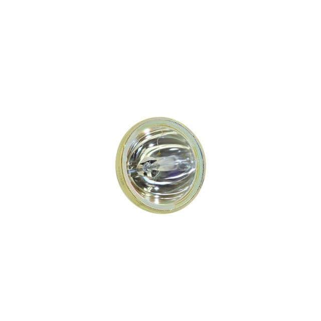
This tutorial centers on the Philips 482213410123 bulb, manufactured by Interlight (SKU: WW-4B2C-9). This is not a standard household bulb, but a specialized halogen or high-intensity discharge (HID) lamp often used in medical, industrial, or projection equipment. Its suitability for this tutorial lies in its well-defined electrical characteristics—typically a 12V, 50W rating—which make it an excellent candidate for learning precision power supply design. Unlike simple resistive loads, this bulb exhibits a low cold resistance (around 0.3 ohms) that rises to approximately 2.88 ohms when hot, demanding a current-limited startup circuit to prevent inrush damage. This tutorial will guide you through designing a constant-current driver that safely powers the bulb from a standard 24V DC supply.
Design Requirements and Specifications
Our goal is to build a robust, efficient driver for the Philips bulb. Key specifications: input voltage 24V DC ±10%, output current 4.17A (to achieve 50W at 12V), output voltage compliance of 0-15V to accommodate the bulb’s cold-to-hot transition, and a startup current limit of 2A for 100ms to protect the filament. Efficiency should exceed 85% to minimize heat. The circuit must include overcurrent protection and a soft-start feature. We will use a step-down (buck) topology due to the 24V input and 12V output requirement.
Step-by-Step Design Process with Calculations
First, determine the switching frequency. Choose 100 kHz as a balance between inductor size and switching losses. Calculate the duty cycle: D = Vout / Vin = 12V / 24V = 0.5 (50%). For the inductor, use the formula L = (Vin - Vout) D / (ΔIL fsw), where ΔIL is the inductor ripple current, set to 30% of Iout (1.25A). Thus, L = (24V - 12V) 0.5 / (1.25A 100,000) = 48 µH. Select a standard 47 µH inductor with a saturation current above 5A. For the output capacitor, target a voltage ripple of 50 mV: Cout = ΔIL / (8 fsw Vripple) = 1.25A / (8 100,000 0.05V) = 31.25 µF. Use a 47 µF, 25V ceramic capacitor with low ESR. For the soft-start, a simple RC network on the controller’s SS pin: choose Rss = 10kΩ and Css = 1µF for a time constant of 10ms, achieving the 100ms limit.
Component Selection Rationale for the Complete BOM
For the controller IC, select the LT3845 or a similar synchronous buck controller with adjustable current limit. Its internal 5V reference simplifies soft-start design. The power MOSFETs: choose a 30V, 50A N-channel device like the IRFZ44N for the high-side, and a 30V, 30A one for the low-side synchronous rectifier (e.g., IRFZ24N). These withstand inrush and have low Rds(on) (~0.02 ohms) for efficiency. The inductor: a 47 µH, 5A shielded toroid (e.g., Coilcraft MSS1278-473). Diodes: a Schottky diode (e.g., 1N5822) for the bootstrap circuit. Input capacitor: 100 µF, 50V electrolytic plus a 1 µF ceramic for high-frequency decoupling. Output capacitor: as calculated, a 47 µF, 25V ceramic. Resistors: 1% tolerance for current sense (0.01 ohm, 3W wirewound) and voltage divider. A 5A fuse on the input for safety.
Simulation Tips and What to Look For
Simulate the circuit in LTspice or a similar tool. Use a bulb model: a resistor that starts at 0.3 ohms and transitions to 2.88 ohms after 100ms (use a voltage-controlled switch with a timer). Key observations: verify the soft-start limits current to 2A initially, then ramps to 4.17A. Check the inductor current ripple—it should be triangular with a 1.25A peak-to-peak amplitude. Confirm the output voltage stabilizes at 12V under steady-state. Look for voltage spikes on the switching node (should be below 30V). Ensure the MOSFET gate drive signals are clean, with no overlap causing shoot-through. Adjust the soft-start capacitor value if the inrush exceeds 2.5A.
Prototype Build and Testing Methodology
Build the circuit on a perfboard or a custom PCB. Start with the power stage: solder the inductor, MOSFETs, and capacitors. Add the controller IC and its support components (bootstrap diode, resistors). Use thick traces or wire for high-current paths (at least 18 AWG). Test methodology: first, without the bulb, apply 24V and verify the output is 0V (soft-start disabled). Then, connect a 1-ohm, 50W resistor as a dummy load. Power up: measure output voltage—it should be 12V ±0.5V. Use an oscilloscope to probe the switching node (drain of high-side MOSFET): expect a square wave from 0 to 24V at 100 kHz. For the bulb test, connect it with short, heavy leads. Monitor the current with a clamp meter: it should rise gradually from 2A to 4.17A over 100ms. Check for overheating: the inductor and MOSFETs should stay below 85°C after 5 minutes.
Performance Verification and Optimization
Measure efficiency: Pin = Vin Iin, Pout = Vout Iout. With a 24V input and 4.17A output, expect Iin around 2.2A at 85% efficiency (Pout=50W, Pin=52.8W). If lower, check for MOSFET gate drive timing or excessive inductor core loss. Verify ripple: output voltage ripple should be under 50 mV p-p; if higher, increase output capacitance to 100 µF. Test the soft-start: use a storage oscilloscope to capture the current waveform during startup; if it overshoots, increase Css to 2.2 µF. For optimization, replace the inductor with a lower DCR type (e.g., 0.01 ohm) to cut losses. Add a heatsink to the high-side MOSFET if its temperature exceeds 90°C. Finally, perform a 24-hour burn-in test to confirm reliability. This design ensures the Philips bulb operates within its specifications, extending its lifespan and delivering consistent light output.