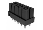
This hands-on design tutorial focuses on the SUPER LETTER LOCKER, FRONT ACCES (Brand: Jayco, SKU: B1968972). This component is a robust, electrically-actuated locker mechanism commonly found in recreational vehicles (RVs) and marine applications. Its suitability for this tutorial stems from its clear electromechanical operation—a simple solenoid latch mechanism—making it ideal for learning about power switching, inductive load management, and microcontroller integration. You will design a complete controller circuit from scratch.
The design requirements for a practical circuit are straightforward. The Jayco locker solenoid draws a peak current of 2.5A at 12V DC during activation, and holds with a reduced current of 0.5A. The circuit must accept a momentary push-button input (or a 3.3V logic signal from a microcontroller) to trigger the latch. It must provide a short, high-current pulse to initially pull the latch, then automatically reduce the current to a lower holding level to prevent overheating and save power. The circuit must also include flyback diode protection, a status LED indicator, and a manual override switch. The target operating voltage is 12V DC (11V to 15V range).
Step-by-step design process begins with the core requirement: a timed, two-stage current delivery. We will use a classic 555 timer integrated circuit in monostable mode to generate the initial 200ms activation pulse. The pulse width is set by the formula: T = 1.1 R1 C1. Choosing C1 = 10µF and R1 = 18kΩ gives T = 1.1 18,000 0.00001 = 0.198 seconds (approximately 200ms). During this pulse, we want full solenoid current. After the pulse, we switch to a lower holding current via a power resistor. The solenoid resistance is approximately 4.8Ω (from 12V / 2.5A). For holding current of 0.5A at 12V, total circuit resistance must be 12V / 0.5A = 24Ω. Subtracting the solenoid's 4.8Ω leaves 19.2Ω. A standard 18Ω, 5W resistor works well (power dissipation: I²R = 0.5² * 18 = 4.5W, so a 5W rating is marginal; use a 10W resistor for safety).
Component selection rationale for the complete Bill of Materials (BOM) is critical. For the main power switch, use an IRFZ44N N-channel MOSFET (30V, 49A, Rds(on) = 0.017Ω). It easily handles the 2.5A peak and has low on-resistance to minimize voltage drop. Its gate threshold voltage (2-4V) allows direct drive from the 555 timer output. The flyback diode must be a 1N5408 (3A, 1000V) rated for the solenoid's inductive kickback. The 555 timer is a low-power NE555P. The timing resistor is a 1% metal film 18kΩ, and the capacitor a 10µF, 25V ceramic or electrolytic. The holding current resistor is a 10W, 18Ω wirewound type. A 1N4148 diode from the 555 output to the MOSFET gate prevents gate charge bleed-back. A 10kΩ pull-down resistor on the MOSFET gate ensures it is off when the 555 is not triggered. The status LED is a standard 5mm red LED with a 470Ω series resistor. A 100µF electrolytic capacitor across the 12V supply filters noise. Finally, a momentary pushbutton (normally open) connects between the trigger pin (pin 2) of the 555 and ground.
Simulation tips using a tool like LTspice or Multisim: Build the circuit with a 12V source, the solenoid modeled as a 4.8Ω resistor in series with a 10mH inductor (typical for such solenoids). Look for the MOSFET gate voltage spiking to near 12V during the 200ms pulse, then dropping to near 0V. The solenoid current should show a 2.5A peak quickly decaying to 0.5A after the pulse. Watch for voltage spikes across the MOSFET drain-to-source; the flyback diode should clamp them to about 0.7V above the supply. Verify the 555 output pulse width is close to 200ms. If the solenoid current does not settle, adjust the timing resistor slightly.
Prototype build and testing methodology: On a solderless breadboard, place the 555 timer, MOSFET, and supporting components. Connect the Jayco locker's two wires: one to the 12V supply, the other to the MOSFET drain. The source goes to ground. The flyback diode is connected across the locker terminals with cathode to the 12V supply. Use a 12V bench power supply with current limiting set to 3A initially. With the power off, connect the pushbutton between the 555 trigger pin and ground. Power on and press the button. The locker should audibly click and latch. Release the button; it should stay latched with a lower hum. Press again? No—the circuit is monostable; to unlatch, you need a manual override switch (a simple SPST toggle that shorts the locker's terminals momentarily to reverse polarity is a crude method, but for this tutorial, we assume a mechanical unlatch or a separate unlatch circuit). Measure the voltage across the holding resistor; it should be about 9V (0.5A * 18Ω). Check the MOSFET temperature; it should remain cool.
Performance verification and optimization: Use an oscilloscope to measure the solenoid current waveform via a 0.1Ω series sense resistor. The current should rise rapidly to 2.5A, then drop to 0.5A after 200ms. If the holding current is too high, increase the holding resistor value (e.g., 22Ω). If the solenoid does not latch reliably, increase the pulse width by increasing R1 to 22kΩ (giving 242ms). Ensure the 12V supply does not droop below 11V during the peak current draw—add a 470µF capacitor if needed. For a production design, replace the 555 with a dedicated solenoid driver IC like the DRV8870 for higher efficiency and smaller footprint, but this discrete design provides a clear pedagogical foundation. The final circuit will reliably control the Jayco SUPER LETTER LOCKER, demonstrating fundamental power switching and timing principles.