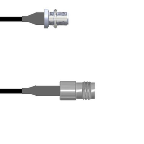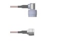

This guide addresses the reliability and quality assurance considerations for the CBL ASSY N TO TNC JCK RG174 2.5M (Brand: Amphenol Custom Cable, SKU: Q-1U04G00032.5M), a coaxial cable assembly terminated with N-type male and TNC female connectors on RG174 cable. As a professional procurement engineer, understanding the specific reliability parameters for this component is critical for system performance, especially in RF and microwave applications where signal integrity and mechanical durability are paramount.
Reliability Standards and Qualifications: This cable assembly should be evaluated against industry standards such as IPC/WHMA-A-620 for cable and wire harness assemblies, which defines acceptance requirements for crimping, soldering, and connector attachment. Additionally, MIL-PRF-39012 for RF connectors and MIL-C-17 for coaxial cables provide relevant qualification benchmarks. Amphenol Custom Cable typically tests to these standards, ensuring the assembly meets insertion loss, VSWR, and impedance specifications (50 ohms for RG174). The assembly should also comply with RoHS and REACH directives for environmental compliance. For reliability qualification, request a manufacturer's test report confirming electrical continuity, dielectric withstand voltage, and mechanical pull tests on the connector-to-cable interface.
Accelerated Life Testing and Results Interpretation: Accelerated life testing (ALT) for this cable assembly often employs temperature cycling (e.g., -55°C to +125°C for 500 cycles) and vibration testing (random vibration per MIL-STD-202, Method 214). These tests simulate years of thermal stress and mechanical fatigue. Results showing no increase in insertion loss beyond ±0.5 dB, no intermittent opens, and no connector backout indicate robust performance. ALT data can be used to estimate the activation energy for failure mechanisms like conductor fatigue or dielectric breakdown. For RG174, common failure modes include shield braid cracking under repeated flexure, so accelerated aging should include flexure testing (e.g., 10,000 cycles at 90-degree bend radius). The Arrhenius model is often applied to extrapolate life at normal operating temperatures, but care is needed as RG174's PVC jacket may degrade faster than the conductor.
Failure Rate Calculations (FIT Rates) and MTBF Considerations: For passive components like this cable assembly, failure rates are typically low, with FIT (Failures In Time) rates in the range of 10-100 FIT per billion hours for the cable and connector interfaces when used within rated conditions. MTBF (Mean Time Between Failures) is often not directly applicable, as these assemblies are not repairable; however, reliability is expressed as a failure probability over time. A typical target might be <1% failure over 10 years at 25°C ambient. To calculate FIT, use MIL-HDBK-217F for cable assemblies, factoring in connector type (N-type and TNC), cable type (RG174), and environment (ground benign or fixed ground). The connector interface is the most likely failure point due to mating cycles and corrosion. For critical applications, a reliability demonstration test with zero failures over a defined number of cycles (e.g., 50,000 mating cycles) can validate low FIT rates.
Environmental Stress Screening and Burn-In Procedures: Environmental stress screening (ESS) is recommended for high-reliability applications. For this assembly, a burn-in procedure should include: thermal cycling from -40°C to +85°C for 10 cycles, with continuous RF monitoring to detect intermittent failures. Vibration screening per MIL-STD-202, Method 204 (5-2000 Hz, 2.5g) for 30 minutes per axis can identify loose connectors or cable defects. After screening, perform a 24-hour DC resistance and capacitance stability test at rated temperature. This screens out infant mortality failures due to poor crimps or assembly defects. Note that burn-in should not exceed the cable's rated temperature limits to avoid premature aging.
Counterfeit Detection Methods Specific to This Component Type: Counterfeit coaxial cable assemblies often use substandard cable or connectors. Detection methods include: visual inspection for connector plating quality (e.g., nickel or gold plating thickness via XRF spectroscopy), measuring cable dielectric diameter (RG174 must have 1.52mm ±0.1mm inner conductor and 2.95mm ±0.2mm outer diameter), and verifying impedance using time-domain reflectometry (TDR) (should be 50 ohms ±2 ohms). Check for inconsistent labeling on the cable jacket (Amphenol branding, part number, and date code). Counterfeit assemblies may have lower shield coverage (RG174 requires >90% braid coverage). Also, test insertion loss at 1 GHz (typically <0.5 dB per meter for RG174) to detect lower-quality cable. Request a Certificate of Conformance (CoC) from an authorized distributor and perform a 3-point dimensional check on the N and TNC connectors per MIL-STD-348.
Incoming Inspection Best Practices: Follow a sampling plan per ANSI/ASQ Z1.4 (AQL 1.0% for critical, 2.5% for major defects). Visual inspection under 10x magnification for connector damage, scratches, or plating defects. Perform electrical tests: DC resistance of center conductor (<10 milliohms) and shield continuity, insulation resistance (>1000 megohms at 500V DC), and dielectric withstand voltage (1500V RMS for 1 minute). Use a network analyzer to measure VSWR (<1.2:1 from DC to 3 GHz) and insertion loss (compare to manufacturer's datasheet). Dimensional checks: verify cable length is 2.5M ±1% and connector mating dimensions per standards. For high-reliability lots, perform a 100% RF sweep test. Document all results for traceability.
Storage and Handling Requirements to Maintain Reliability: Store in a clean, dry environment at 15-35°C and <60% relative humidity to prevent connector corrosion and cable jacket degradation. Use anti-static bags (since RG174 has a PVC jacket that can attract dust) and avoid direct sunlight or ozone sources. Handle with care to avoid kinking or bending the cable below its minimum bend radius (25mm for RG174). When mating connectors, use proper torque (N-type: 0.7-1.1 Nm, TNC: 0.3-0.5 Nm) to prevent thread damage. Do not exceed 500 mating cycles for the TNC connector to maintain RF performance. For storage longer than 12 months, consider dessicant packs and periodic inspection for connector oxidation.
End-of-Life Management and Obsolescence Planning: Amphenol Custom Cable may discontinue this assembly if the RG174 cable or connectors become obsolete. Plan for a 2-year lifecycle by maintaining a safety stock of 10-20% of annual usage. Identify alternate sources: similar assemblies using RG316 (higher temperature rating) or RG58 (thicker cable) may be drop-in replacements but require impedance re-verification. For long-term support, request a last-time buy (LTB) notification from the manufacturer and pre-qualify a substitute assembly. Maintain documentation of the assembly's electrical and mechanical parameters to facilitate future redesigns. Consider a reliability prediction using the manufacturer's historical failure data to set appropriate replacement intervals (e.g., replace after 10 years in fixed installations).