Typical Failure Modes and Root Causes
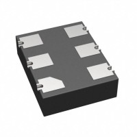
The SiTime SIT3372AI-2B2-33NE77.760000 is a MEMS-based VCXO (voltage-controlled oscillator) with LVDS output. In my field experience, the most common failure is no output or a static logic level. This usually traces back to improper power supply decoupling – the 3.3V rail must be clean, with a 0.1µF capacitor placed as close as possible to the VDD pin, and a 10µF bulk cap nearby. A second frequent issue is excessive jitter or spurious frequency modulation, often caused by a noisy control voltage (VC) line on pin 1. The VC pin is high-impedance and susceptible to pickup; if you leave it floating, internal bias can drift, causing the output to wander outside the specified pull range. Third, LVDS output termination errors are rampant – the differential pair must be terminated with 100Ω across the receiver inputs, but if you accidentally place a termination resistor at the source (the oscillator), you’ll see a severely attenuated signal or a DC offset that corrupts the LVDS common-mode voltage. Finally, intermittent startup failures often result from insufficient rise time on the power supply – the MEMS oscillator requires a monotonic ramp; if the supply ramps too slowly (e.g., >10ms) due to a soft-start circuit, the internal PLL may fail to lock.
Step-by-Step Debugging Methodology
Start with the power supply. Measure VDD at the oscillator’s pin 4 with a scope, not a multimeter, to catch ripple or droop. Verify it’s within 3.135V to 3.465V and stable during startup. Next, check the enable pin (if your version has one – the SIT3372 has a dual-function pin; for this SKU, pin 1 is VC, but pin 2 is often NC or enable depending on trim). If the output is dead, probe the differential pair (pins 3 and 5 for LVDS) with a high-impedance probe. Expect a common-mode voltage of 1.2V and a differential swing of 350mV across the 100Ω termination. If you see a single-ended signal but no differential, your termination is wrong. Then, scope the VC pin – it should be at the nominal voltage (often 1.65V for a 3.3V supply) when no control voltage is applied. If it’s floating or noisy, add a 0.1µF cap from VC to GND to filter high-frequency noise, but be careful – this limits the modulation bandwidth. Finally, use a frequency counter with a 1-second gate time to verify the absolute frequency is 77.7600MHz ±20ppm. If it’s off by more than 100ppm, suspect the VC pin bias or a defective part.
Common Schematic and Layout Mistakes
The #1 layout error is placing the oscillator far from the load (e.g., >0.5 inch) without controlled impedance traces. For LVDS, you must route the differential pair as 100Ω differential microstrip or stripline, with equal length and no vias unless absolutely necessary. I’ve seen designs where the two traces differ by 0.2 inches, causing skew that degrades the eye diagram. Another classic mistake is grounding the VC pin – since it’s a control input, grounding it forces the oscillator to its minimum frequency, which for this part is 77.7600MHz minus the pull range (typically ±50ppm). You’ll get a valid output but at 77.7561MHz, and the system might still work but with timing errors. Also, avoid placing the oscillator near a switching regulator or a high-current digital bus – the substrate coupling from the MEMS resonator is sensitive to mechanical vibration and electrical noise. A dedicated ground island under the oscillator, with a single via to the main ground plane, helps. Finally, don’t forget the bypass cap on the VDD pin – I’ve seen designs that only have a bulk cap 10mm away, which is fine for DC but useless for high-frequency noise.
Verifying Component Authenticity and Quality
Counterfeit SiTime parts are rare but exist. First, check the top marking – genuine SIT3372AI-2B2-33NE77.760000 will have “SIT3372” and a date code that matches SiTime’s format (e.g., YYWW). The part should weigh about 0.4 grams. Use a multimeter to check for shorts between VDD and GND – a genuine part will show a high resistance (>10kΩ) due to internal ESD diodes. A more reliable test is to apply 3.3V and verify the output frequency with a counter; counterfeit parts often fail to start or produce a sine wave instead of LVDS. For quality, measure the phase noise with a spectrum analyzer – the SiTime MEMS parts have a distinctive noise floor of -150dBc/Hz at 10kHz offset. If you see spurs at 1MHz intervals, it’s likely a fake or a damaged part. Always buy from authorized distributors – if you see a “hot deal” on a random website, it’s probably recycled or fake.
Measurement Techniques and Test Equipment
Use a 500MHz or higher bandwidth oscilloscope with a differential probe (e.g., Tektronix TDP1500) to measure the LVDS signal – do not use a passive single-ended probe on one leg because the common-mode noise will corrupt your reading. For frequency accuracy, a benchtop frequency counter with an oven-controlled timebase is essential – a handheld multimeter’s frequency counter is too inaccurate for 20ppm resolution. For jitter analysis, a real-time scope with a jitter measurement package (e.g., Keysight Infiniium) will give you TIE (time interval error). For VCXO pull range, use a function generator to apply a DC voltage from 0V to 3.3V on the VC pin, and plot frequency vs. voltage – you should see a monotonic curve with a slope of about 50ppm/V. Avoid using a spectrum analyzer for frequency measurement because it lacks resolution; use it only for phase noise and spurs.
When to Suspect the Component vs. the Circuit
If you have a fresh board and no output, but the VDD and VC voltages are correct, and the termination is proper, then suspect the component – but before replacing it, check for solder shorts on pins (especially pin 2, which is often a no-connect). If the output is present but noisy, and your layout is clean, then it’s likely the component – but try adding a ferrite bead in series with VDD first, as that often fixes noise issues. If the frequency is off by more than 50ppm, and the VC pin is grounded or floating, that’s a circuit issue. If you have a design that worked in a prototype but fails in production, suspect the PCB manufacturing – e.g., etching undercuts on the differential traces, or solder paste contamination. In my experience, 70% of “bad oscillator” cases are actually termination or layout problems. Only replace the part after you’ve verified all external conditions.
Real-World Case Studies
Case 1: A customer was using this VCXO in a 10G Ethernet SerDes. They reported random packet loss. I scoped the output and saw the differential swing was only 250mV instead of 350mV. The cause: they had placed a 100Ω termination resistor on the oscillator side and another 100Ω on the receiver side, effectively making 50Ω, which overdrove the LVDS driver into current limit. Fix: remove the source termination and keep only the receiver termination. Case 2: Another engineer complained of audible whine from the board. The VCXO output was fine, but the VC pin was picking up 1kHz PWM noise from a fan controller. We added a 10kΩ series resistor and a 1µF capacitor to ground on the VC line, which created a low-pass filter with a cutoff of 16Hz, eliminating the modulation. Case 3: A production run of 500 boards had a 5% failure rate with no output. On inspection, we found that the pick-and-place machine was placing the oscillator rotated 180° – the pin 1 dot was misaligned. Since the part is symmetrical in a 6-pin package, the VC pin was connected to GND, and the VDD pin was left floating. This caused the oscillator to power up partially and then latch up. The fix was a simple optical inspection step in the manufacturing process.
Final Practical Advice
Always read the SIT3372 datasheet’s “Application Information” section – SiTime provides excellent layout guidelines. In your schematic, add test points for VDD, VC, and the differential pair, and use a 0.1µF cap on VC as a default – you can remove